I lost the first version of this post because of problem in blogger's auto-save function.
Anyway so if you want to get your own raspberry pi os kernel going, I share some cool posts on that in here and expand on them by unpacking some of the assembler code essentially reverse engineering it or "unrolling" the os.
Anyway so if you want to get your own raspberry pi os kernel going, I share some cool posts on that in here and expand on them by unpacking some of the assembler code essentially reverse engineering it or "unrolling" the os.
Setting up your Development Environment
I think the explanation of the 'Roll your own Rapsberry Pi Os' at https://jsandler18.github.io/ pretty much sorts this out I can at least do the favor of confirming that this persons advice definitely does the job so check it out. The post also discusses the background of why we need certain files in the project for instance like the linker scripts and kernel.c files. As a short summary here's the basic work flow:
1 - Write a linker script
This is to make sure the compiler can recombined the boot.S and kernel.c parts
2 - Write a boot.S
This file is to initialize the run time for your kernel and branch into it.3 - Write a kernel.c
This is the actual kernel, we will be using the C run time. Mine looks like this:4 - Compile boot.S, kernel.c
To get some object files


Once you've compiled and launched your own kernel a couple times you might want to try to reverse engineer it to make sure you know it at all its levels of existence as software.
Lets get started!
Reverse engineering a basic ARM bootloader
Of course in order to get hold of the assmbly code for your kernel you need to invoke the cross compiled objdump on your kernel image like so:

So the first thing we do in the boot.S file is define a couple labels and import some as well you don't need to worry too much about these but they are pretty standard linking stuff. I'm more interested in the instructions being defined in the .start label, and if you haven't guessed it, this code is what gets the ball rolling.
The first thing we see there is this weird instruction:
What this command does is essentially use a special feature that arm has called "coprocessors" they are functions on an ARM boards that extend features like caching, memory management stuff, gpu, etc it depends a little on the hardware folks whats going on with these sometimes. The documentation says the following about the p15 register, which is the one we are invoking using the MRC operation:
In order to use these wonderful features we need to invoke the MRC/MCR commands and pass them some arguments and opcodes. The MRC instruction is the following (According to the ARM documentation):
Move to ARM register from coprocessor. Depending on the coprocessor, you might be able to specify various operations in addition.
Which doesn't explain much really, critically it says that this gives access to the coprocessor functions and their functions depend on uhm how they are defined. There's a slightly more helpful Stack overflow post I found here, and it says the following:
MRC stands for "send a command to a coprocessor and get some data back"
So the command and what you get back depends on specific definitions for the co processor. But is meant to service a fetch+do style command basically; do stuff for me and return some information. The command format also needs a little explaining here's how MRC basically works
There's a way to conditionally execute this I'm gonna stick to the non-cond for now. The coproccessors are registers p1-15, here's the breakdown on what they all do. For each of them you can do stuff like read property values and set them with mrc by specifying these opcodes1,2 which can be a range of integer values (we will discuss the one used here below). CRn,m specify additional coprocessor registers; again this are defined according to a table below. And most importantly for us the Rd placeholder is for a register to target with this command - our example here targets it in order to save a copy of the Multiprocessor Affinity Register. Our invocation has opcode1 as 0 and opcode2 as 5, so that means this according to the documentation
So the first thing we do in the boot.S file is define a couple labels and import some as well you don't need to worry too much about these but they are pretty standard linking stuff. I'm more interested in the instructions being defined in the .start label, and if you haven't guessed it, this code is what gets the ball rolling.
The first thing we see there is this weird instruction:
mrc p15,#0,r1,c0,c0,#5
What this command does is essentially use a special feature that arm has called "coprocessors" they are functions on an ARM boards that extend features like caching, memory management stuff, gpu, etc it depends a little on the hardware folks whats going on with these sometimes. The documentation says the following about the p15 register, which is the one we are invoking using the MRC operation:
The CP15 system registers provide control and status information for the functions implemented in the processor. The main functions of the CP15 system registers are:
- Overall system control and configuration.
- Memory Management Unit (MMU) configuration and management.
- Cache configuration and management.
- Virtualization and security.
- System performance monitoring.
In order to use these wonderful features we need to invoke the MRC/MCR commands and pass them some arguments and opcodes. The MRC instruction is the following (According to the ARM documentation):
Move to ARM register from coprocessor. Depending on the coprocessor, you might be able to specify various operations in addition.
Which doesn't explain much really, critically it says that this gives access to the coprocessor functions and their functions depend on uhm how they are defined. There's a slightly more helpful Stack overflow post I found here, and it says the following:
MRC stands for "send a command to a coprocessor and get some data back"
So the command and what you get back depends on specific definitions for the co processor. But is meant to service a fetch+do style command basically; do stuff for me and return some information. The command format also needs a little explaining here's how MRC basically works
MRC{cond}coproc,opcode1,Rd,CRn,CRm{,opcode2}
There's a way to conditionally execute this I'm gonna stick to the non-cond for now. The coproccessors are registers p1-15, here's the breakdown on what they all do. For each of them you can do stuff like read property values and set them with mrc by specifying these opcodes1,2 which can be a range of integer values (we will discuss the one used here below). CRn,m specify additional coprocessor registers; again this are defined according to a table below. And most importantly for us the Rd placeholder is for a register to target with this command - our example here targets it in order to save a copy of the Multiprocessor Affinity Register. Our invocation has opcode1 as 0 and opcode2 as 5, so that means this according to the documentation
At the bottom of the Mulitprocessor Affiinity Register page linked above it give the following example command which looks a lot like what we are dong:
To access the MPIDR, read the CP15 registers with:
MRC p15, 0, <Rt>, c0, c0, 5; Read Multiprocessor Affinity Register
What our code is doing with the Multiprocessor Affinity Register's value is copying it into the r1 , most probably to check that it has a certain setting. The documentation states the following about how the register's value is formatted:

Which says that the CPU ID field looks like this:
Given that the instruction here and's r1 with 3:
It seems that it is checking what the values of the CPU ID are using a bit mask basically. If its not 3 (both bits are on 3 = 11 in binary ) then it halts. Why is it checking if its 3? I think right now this is so that it can make sure its running on one core so it checks the ID to make sure its the last one. Running the code by changing the #3 literal in the boot.S shows that the kernel runs a couple times basically or executes the instructions more than once if you don't make sure you are running on the ID with 3 as the first 2 bits.
To compare different invocations of the mrc and coprocessors its a good idea to scratch around other peoples kernels to see what they are doing with this instruction, here's an example I found on github:
To compare different invocations of the mrc and coprocessors its a good idea to scratch around other peoples kernels to see what they are doing with this instruction, here's an example I found on github:

Clearly it this is to determine the board type. I'm not delving into too much detail about the specific value we are checking and what it means to find this out I need to dig a little deeper in the board data sheets probably but my jury is out on hard confirmations about what opcode 5 does. None-the-less we can be pretty sure this is to make sure our code runs properly on the right board. Moving on!
Reverse Engineering a basic C run time setup
The next snippet of code looks like this:
The mov sp instruction points the stack address at 0x8000 afaik there's some flexibility in which value you use, but it might also depend on your board type. After that we see a ldr instruction here, this is the definition of this operation according to the documentation:
The
LDR pseudo-instruction loads a register with either:- a 32-bit constant value
- an address.
This code is pretty straight forward then; it loads the addresses of where the labels __bss_start and __bss_end are into registers r4 and r9 respectively. It then 0's out the values of registers r5-r8. After all this it issues a b 2f instruction, which means it will branch unconditionally to label 2 and start executing there. We can confirm this by looking at the assembler code for this:

The instruction at 802c reads b 8034 <__start+0x34> shows that it will branch to the cmp r4,r9 instruction which is according to boot.S the first instruction under label 2. After the comparison it does another conditional branch based on whether the two registers are equal or not. If they are it repeats the loop by branching back to _start+0x30 which has this instruction:
stmia r4!,{r5-r8}
The stm instruction stores a set of values constructed from the list registers' values in the braces (here our example is all the registers from r5-r8's a total of 16 bytes). at the address pointed to by the register value specified These register values are written contiguously to the address in memory pointed to by r4. The exclamation suffix means write the final address back to r4. stm has a ia suffix because it will automatically increment r4 after writing to it. This allows us to slam 16 bytes into memory at a time.
Whats happening here may seem odd, but its pretty standard parlance in cleaning out memory sections in order to prep a C run time. Here's some example's from other people's rapsberry pi kernels. This one is also cleaning out the bss, you can see it does some other C/C++ run time prep stuff too:
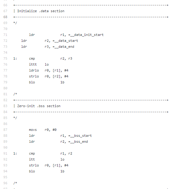
The code in the section labeled "Initialize the .data section" copies stuff out of memory using a ldrlo instruction which reads 4 bytes from the address [r1] which we can see is initialized as __data_init_start then it stores it to the memory address [r2] immediately after using the strlo operation. Very similar structure to what we are doing. This post called "Building Bare metal ARM systems with GNU" shows some more https://www.embedded.com/design/mcus-processors-and-socs/4026075/Building-Bare-Metal-ARM-Systems-with-GNU-Part-2
Okay so lets say we are done setting up our C runtime, the next thing boot.S does is branch to the kernel like so:
The blx instruction is pretty important it means branch with link exchange and it will transfer control to the kernel's main function.
Once it breaks into the kernel it passes it a couple arguments this is the location of the atags structure in memory. I will get into that perhaps in a later post but what I want to focus on here is how the uart_init and kernel main functions look at assembler level.
Here's the kernel main:

Lets break this down. Firs instruction is a push to preserve the r4 and link registers according to the sources I have here this is done because the r4 register holds the atags start address which is passed to the kernel on start. What happens then is the kernel branches immediately to uart_init which looks like this:

Doesn't look like too much of a monster all it does here is essentially shuffle some values around. First instruction puts a 0 into r1 which is being used as a place holder for 0 and clears it for later use as well. The next two instructions constructs the base value for the GPIO reference structure, it does this by first putting 0x1000 in the bottom half of the r3 register value and then using a movt to stick the top 0x3f20 bits in. Here's the documentation on the movt instruction:
Pretty useful stuff if gives you some flexibility in shuffling around byte values. So it makes r3 hold the value 0x3f201000 which we know from the code is the UART_BASE address:
 Then it sets up another offset in the GPIO enum; but this one using r1 (which points to GPIO_BASE via another movt) it moves a value into r2 but I suspect this is only going to make sense later on (lets skip it for now). With those two pointers set up it performs a str instruction using the r0 value which 0, and writing it to r3+0x30 which is UART_CR and if we look at the code again this is exactly what its doing, just setting the memory address pointed to by UART_CR to 0:

Same goes for the r1 str operation of course. We know r1 points to GPIO_BASE, and the str writes to r1+0x94 which is GPPUD.
Okay the rest of the kernel operations are no different to this really they just perform writes to different offsets. I think if you'd like to git gud at reverse engineering these kinds of functions try reversing the rest of the kernel and then looking for some other kernels that do something like this and see if you can reverse engineer out how they do it and where. Have fun!
Whats happening here may seem odd, but its pretty standard parlance in cleaning out memory sections in order to prep a C run time. Here's some example's from other people's rapsberry pi kernels. This one is also cleaning out the bss, you can see it does some other C/C++ run time prep stuff too:
The code in the section labeled "Initialize the .data section" copies stuff out of memory using a ldrlo instruction which reads 4 bytes from the address [r1] which we can see is initialized as __data_init_start then it stores it to the memory address [r2] immediately after using the strlo operation. Very similar structure to what we are doing. This post called "Building Bare metal ARM systems with GNU" shows some more https://www.embedded.com/design/mcus-processors-and-socs/4026075/Building-Bare-Metal-ARM-Systems-with-GNU-Part-2
Okay so lets say we are done setting up our C runtime, the next thing boot.S does is branch to the kernel like so:
ldr r3,=kernel_main
blx r3
The blx instruction is pretty important it means branch with link exchange and it will transfer control to the kernel's main function.
Reverse Engineering Basic UART I/O initialization
Once it breaks into the kernel it passes it a couple arguments this is the location of the atags structure in memory. I will get into that perhaps in a later post but what I want to focus on here is how the uart_init and kernel main functions look at assembler level.
Here's the kernel main:
Lets break this down. Firs instruction is a push to preserve the r4 and link registers according to the sources I have here this is done because the r4 register holds the atags start address which is passed to the kernel on start. What happens then is the kernel branches immediately to uart_init which looks like this:
Doesn't look like too much of a monster all it does here is essentially shuffle some values around. First instruction puts a 0 into r1 which is being used as a place holder for 0 and clears it for later use as well. The next two instructions constructs the base value for the GPIO reference structure, it does this by first putting 0x1000 in the bottom half of the r3 register value and then using a movt to stick the top 0x3f20 bits in. Here's the documentation on the movt instruction:
Move Top. Writes a 16-bit immediate value to the top halfword of a register, without affecting the bottom halfword.
Same goes for the r1 str operation of course. We know r1 points to GPIO_BASE, and the str writes to r1+0x94 which is GPPUD.
Okay the rest of the kernel operations are no different to this really they just perform writes to different offsets. I think if you'd like to git gud at reverse engineering these kinds of functions try reversing the rest of the kernel and then looking for some other kernels that do something like this and see if you can reverse engineer out how they do it and where. Have fun!
Reading and references
- Bare bones RaspberryPi OS https://wiki.osdev.org/Raspberry_Pi_Bare_Bones
- Vector.s https://github.com/dwelch67/raspberrypi/blob/master/boards/cpuid/vectors.s
- https://www.techrepublic.com/blog/european-technology/build-your-own-os-using-the-raspberry-pi/
- https://jsandler18.github.io/
- http://infocenter.arm.com/help/index.jsp?topic=/com.arm.doc.dui0068b/CIHEEIDJ.html
- http://infocenter.arm.com/help/index.jsp?topic=/com.arm.doc.ddi0464e/CHDGECEI.html
- http://infocenter.arm.com/help/index.jsp?topic=/com.arm.doc.ddi0360f/CHDGIJFB.html
- C0 Main ID Register http://infocenter.arm.com/help/index.jsp?topic=/com.arm.doc.ddi0360f/I65012.html
- Load Register Byte http://infocenter.arm.com/help/index.jsp?topic=/com.arm.doc.dui0802a/LDRB_imm.html
- BCM2835 Specifications https://www.raspberrypi.org/documentation/hardware/raspberrypi/bcm2835/README.md
- ARM11 Tech reference manual http://infocenter.arm.com/help/index.jsp?topic=/com.arm.doc.ddi0301h/index.html
- c0 Coprocessor Registers http://infocenter.arm.com/help/index.jsp?topic=/com.arm.doc.ddi0464f/index.html
Comments
Post a Comment